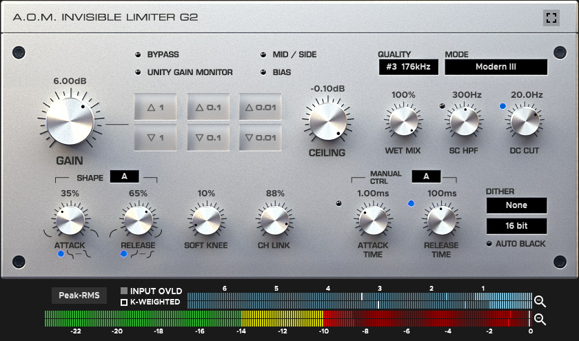
Invisible Limiter G2
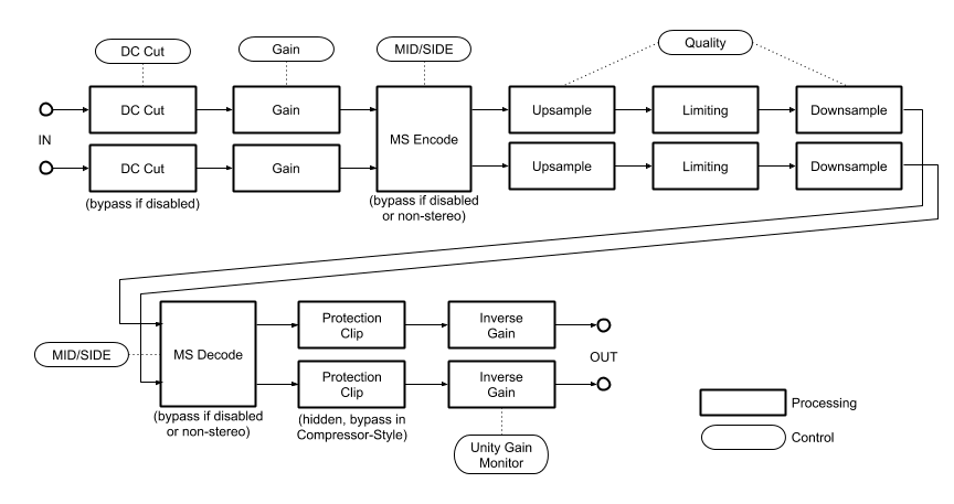
Block Diagrams
Overall
Limiter Sub-block

Operation Modes
Invisible Limiter G2 has two operation modes.
Easy mode includes essential controls for final brick-wall limiting. Advanced mode is for experts, allows full control of the limier. There is no difference in internal algorithm of the limiter.

Modes can be toggled by square-shaped button at the right top of GUI or “Switch to [Advanced/Easy] mode” menu.

Gain Controls

Gain knob Controls the gain amount applied before limiting.
Six-segment gain buttons enable stepwise control in 1dB, 0.1dB, 0.01dB.
Ceiling knob controls threshold which the output signal should not exceed. You can set this control to lower value if you use the limiter in tracks or buses. 0.00dB is not recommended when using dither.
Bypassing and Unity Gain Monitoring
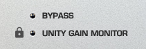
When Bypass indicator is active (blue), plugin bypasses all processing.
When Unity Gain Monitoring indicator is active (blue), the negative of input gain is added to output gain. Unity gain monitoring helps users to monitor output at the same level of input. Try toggling bypass button after unity gain monitoring enabled.
Overall Tweaks

Quality selector controls internal processing frequency. Actual internal frequency is displayed beside of the quality setting.
Note
It’s not true that the higher value always brings ‘good’ result. Choose this value carefully with your own ears.
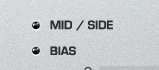
- Mid / Side swtich
toggles MS Encode/Decode sub-blocks. When enabled, most of signal path works for M/S pair instead of L/R pair. Mid/Side processing is available only in stereo channel configuration. Under other channel configurations, the state of this switch is just ignored.
- BIAS switch
makes sound fat/warm a bit.

Mode selector controls current processing mode (limiting algoithm).
- Modern
This mode has been newly introduced in Invisible Limiter G2.
- Modern II
Cleaner and more transparent than Modern mode.
- Modern III
Cleaner and more transparent than Modern II mode.
- Modern IV
Cleaner and more transparent than Modern III mode.
- Modern V
Cleaner and more transparent than Modern IV mode.
- Suppress
This mode is similar to Invisible Limiter’s Suppress mode.
- Clip
This mode is similar to Invisible Limiter’s Clip mode.
- Through
This mode is similar to Invisible Limiter’s THRU mode.
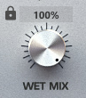
Wet Mix knob controls mix ratio between input signal and processed signal. If you’re intended to do parallel compression, this control is useful.
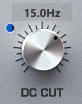
When DC Cut lamp is lighting, the high-pass filter before limiting is engaged.
Peak Detector Tweaks
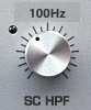
SC HPF (Sidechain hi-pass filter) knob controls cutoff frequency of high-pass filter inserted into internal envelope detector chain. This feature can be used to exclude bass frequency from peak detection, or to configure the limiter as a simple de-essor.
Reduction Generator Tweaks
Shape Controls
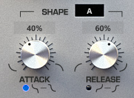
- Attack Knob
Controls transition curve of reduction amount in attack phase.
- Attack Shape LED Button
When enabled (blue), the shape of transition curve in attack phase is changed from exponential to sigmoidal.
- Release Knob
Controls transition curve of reduction amount in release phase.
- Release Shape LED Button
When enabled (blue), the shape of transition curve in release phase is changed from exponential to sigmoidal.
- Shape Mode Select
Changes behavior of internal reduction-shape control. This will be effective only in Modern mode.
See Fig. 1 and Fig. 2 for curve shapes.
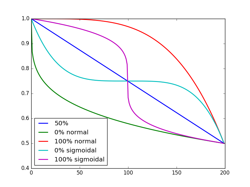
Fig. 1 Reduction curves for several attack shape settings. Time series, linear scale, from 0dB to 6dB reduction.

Fig. 2 Reduction curves for several release shape settings. Time series, linear scale, from 6dB to 0dB reduction.
Soft Knee
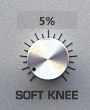
Soft knee knob controls soft knee amount. Fig. 3 shows compression curves for typical settings.

Fig. 3 Compression curves for typical soft knee settings. Log scale.
Channel Link
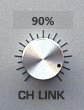
Controls channel link amount. 0% means fully unlinked. 100% means fully linked.
Manual Attack/Release Controls

- Attack Time LED Button
Activate or deactivate manual attack time behavior.
- Attack Time Knob
Controls attack time. When manual attack is enabled, the limiter enters ‘Compressor-Style’ because it cannot guarantee nonexistence of peak exceeding in output signal.
- Release Time LED Button
Activate or deactivate manual release time behavior.
- Release Time Knob
Controls release time.
- Release Mode Select
Changes internal behavior related to manual release time setting. This will be effective only in Modern mode.
Meters and Indicators
Compressor-Style indicator

Compressor-Style indicator becomes visible when:
Wet Mix control is set otherwise than 100%.
Mid / Side processing is enabled.
Manual Attack Time is enabled.
SC HPF is enabled.
Note
When this indicator is visible, the limiter allows peak exceeding in output signal.
Reduction Meter

Shows current reduction amount.
- Bar
Represents the latest value of reduction amount.
- Single Blue Segment
Represents short term maximum value of reduction amount.
- Single White Segment
Represents long term maximum value of reduction amount. Can be reset by clicking meter.
Clicking magnifier icon toggles zoom level of the meter.
Output Level Meter

Shows current output level.
- Bar
Represents the latest RMS/VU level of output signal.
- Single Segment (Green / Yellow / Red)
Represents the latest sample peak level of output signal.
- Single Segment (White)
Represents current value of CEILING parameter.
Clicking magnifier icon toggles zoom level of the meter.
Meter Settings

- Peak-RMS
Shows RMS and Peak value.
- Peak-VU
Shows VU and Peak value.
- K-12, K-14, K-20
Shows RMS and Peak value. Meter scale is optimized for K-12/K-14/K-20.
- K-12/VU, K-14/VU, K-20/VU
Shows VU and Peak value. Meter scale is optimized for K-System [1] K-12/K-14/K-20.
Note
Integration time of the RMS/VU meter is fixed to 600ms to follow K-System specification.
Note
Static offset is added to raw RMS/VU computed value to follow AES17 standard.

When K-Weighted Switch is active (filled), “K” frequency weighting (specified in ITU-R BS.1770-3 Annex 1 [2]) is applied before RMS/VU calculation.

Input Overload Indicator becomes active (red) when sample peak exceeds 0dBFS at the entry of plugin.
Footnotes
Dither

- Dither Type Select
Selects dither type. See the table below for each type.
- Dither Bit Depth Select
Selects dither bit depth.
- Auto Black Button
When active, dither signal is automatically muted for very low level input signal.
Name |
Description |
|---|---|
-— |
Does nothing. Dithering block is completely bypassed. |
Flat |
Applies 2-LSB TPDF dither. |
Acoustic |
Applies original colored dither. |
Electronic |
Applies original noise-shaped dither. |
Truncate |
Truncates signal to selected bit-depth. No dither noise is added. |